When I showed Ataru playing At Doom’s Gate to my wife, she thought I had built some sort of advanced ultrasonic pest repellent. I died a little inside. Apparently, in her hierarchy of priorities, preventing neighbourhood dogs from pooping in front of our house ranks slightly above coaxing a custom-built 8-bit computer into doing something interesting. I don’t blame her.
Good thing I’m a self-motivated person.
Ataru, when switched on, currently gives the impression of being the idiot child of a TRS-80 and a ZX81. It has opinions, but no way to express them. In people, I consider this a virtue. But Ataru is not people.
We’ve been through a lot together. If there is a hell, we probably already have first-class tickets booked. It would be a shame to spend eternity with something that cannot even talk. That would make hell… well, hell.
So, much like Pinocchio needed a soul, Ataru needs a mouth.
And I am determined to give it one.

Breakfast and Serial
There are myriad ways to give a voice to Ataru: a video display processor, a programmable sound generator, perhaps even something more ambitious. In the world of voices, the first would be David Gilmour, the second Richard Wright. I instead opted for Roger Waters: serial communication. When it works, it is effective, governs both input and output, and requires almost no additional peripherals to get up and running.
The biggest motivation for going down this route is the ability to load programs over serial, which saves me from constantly flashing EEPROMs. Every tiny change currently requires dislodging and reprogramming the ROM chip, a process that eats away at my sanity and the chip’s physical integrity in equal measure. At some point you start looking at ZIF sockets the way sailors look at lighthouses: with hope, relief, and a vague sense that life could have been easier.
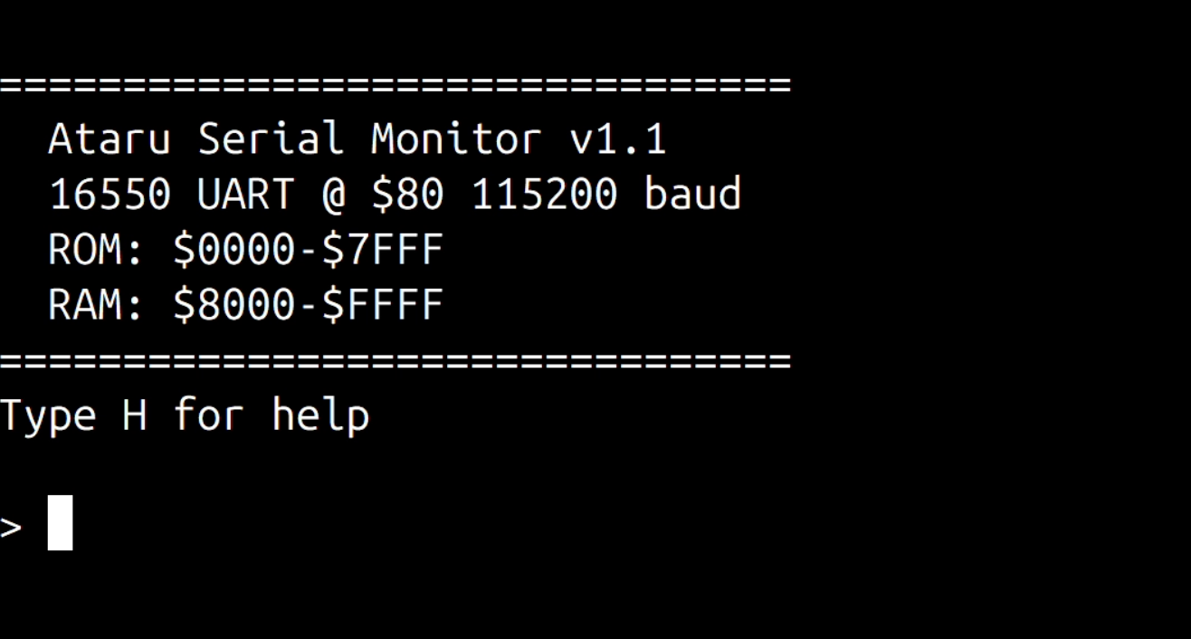
Anyway, going for a serial module meant one thing: I had to write a monitor.
Today we take operating systems for granted: bloated, multi-layered behemoths that handle everything, from file systems to existential updates, and now apparently even age verification. A monitor is a primitive resident program that lives in ROM. It is the absolute bare minimum of software to make a pile of chips feel like a computer.
If a modern operating system is a personal assistant who manages your schedule, a monitor is more like a prison warden. It offers a handful of commands that let you peek (look at the contents of a memory address), poke (forcibly shove a new byte into that address), run (point the CPU at an address and hope for the best), and perform basic I/O (send or receive a character from the outside world).
Without a monitor, Ataru is just a fast, expensive heater. One that happens to scare dogs away.
With a monitor, we can finally talk to it. Type a command in a terminal, and the monitor interprets the keystrokes and manipulates the hardware on your behalf.
Of course, this assumes the machine is actually capable of talking over serial in the first place. That detail turned out to be… negotiable.
La Famiglia
Traditionally, there were two ways to implement serial communication on a Z80-based computer. The first is to use the Z80 DART (Dual Asynchronous Receiver-Transmitter). The second involves pairing the Z80 CTC (Counter/Timer Channel) with the Z80 SIO (Serial Input/Output controller).
Fortuitously, I had a couple of SIOs and a CTC available, so no sleepless nights were lost deciding which approach to take. It should be noted that the CTC and SIO have a peculiar relationship. Together they form a functional serial interface; separately they behave like Dr Jekyll and Mr Hyde.
There are actually three variants of the SIO chip, named /0, /1 and /2. If the Internet is to be believed, /0 is the GOAT, while /1 and /2 should be avoided like the plague. As fate would have it, I had a single /0 and a generous supply of /1s and /2s.
For the record, these were chips purchased from AliExpress: second-hand, possibly third-hand, and quite possibly recovered from the ruins of some long-forgotten electronics project. The solder joints on these chips make the returning soldiers from Verdun look like they’ve just woken up from a well-rested night’s sleep.
After building a harness to connect three strips of breadboard to the backplane, I began wiring the CTC. The goal was simple: verify the Z80 could talk to it, and that the CTC could talk back.
The CTC integrates with the Z80 interrupt system and is typically used for generating baud clocks for the SIO. It has four independent channels that can be configured in different modes, including counters, timers and event-triggered inputs. I wrote a small test program that configured the CTC to generate periodic interrupts; the handler simply toggled the on-board LED. A couple of EEPROM flashes later, the LED was blinking.
Success.
Next came the SIO. Thankfully, a kind soul named Mario Blunk compiled an excellent tutorial on programming Z80 peripheral chips. I followed it closely, with the inevitable tweaks required to adapt things to Ataru. However, two things proved particularly challenging – no doubt because I’m an idiot.
The first was the system clock. Ataru runs at 10 MHz, primarily because it’s a nice round number and, well, it was the only suitable oscillator that I had on hand. Unfortunately, round numbers and serial communication are not friends.
In timer mode, the CTC generates output frequencies using the following relationship:
where the time constant is an integer between 1 and 256, and the prescaler is either 16 or 256. The SIO, meanwhile, expects a clock that is 16x the baud rate. For a baud rate of 9600, the required clock is therefore:
If we use the CTC with a prescaler of 16, the highest frequency we can obtain is:
To obtain the desired clock for the SIO, the time constant would need to satisfy:
Since the time constant must be an integer, we have to choose either 4 or 5. The closer option is 4, which yields:
Dividing that by 16 gives the resulting baud rate:
This is close to 9600 baud, but not quite close enough to make everyone comfortable.
The second problem was more mundane: never underestimate breadboard impedance and connectivity issues. This is foreshadowing.
Echoes : UART or You Aren’t
After some struggling, I managed to get Tera Term to output the letter “A” repeatedly. Ataru started babbling. After a bit more struggling, I managed to echo characters back from the terminal. This felt like a monstrous achievement; I was already picturing terminal games in my head.
The next step was to clean up the initialisation code, implement proper send and receive routines, and wrap everything into subroutines that didn’t needlessly clobber registers. I then added routines for printing strings and reading line input, laying the groundwork for a basic command-line interface.
Or so I thought.
When I began testing the code, I assumed that the slight baud rate error (less than 2%) would not cause any real issues. I convinced myself it would be fine. It turned out to be the kind of fine where the text output resembled a round of Wheel of Fortune: half the letters missing and bells ringing at unpredictable moments.
I tried tweaking Tera Term’s serial settings to match the slightly skewed baud rate as closely as possible, but errors kept appearing. Characters would occasionally corrupt, messages would lose letters, and my early optimism started to fade.
So I started looking for patterns. I didn’t want to believe everything was caused by baud mismatch. And there was a pattern. Characters seemed to frequently lose their least significant bit. For example, the string “Monitor” would appear as “Lnhtnr“. That clearly pointed to something more sinister than a slightly off-clocked serial line.
Just my luck.
After some probing, I traced the problem to a faulty D0 pin on the SIO. It was intermittently misbehaving for reasons known only to the silicon gods. So much for the GOAT.
By this point, the SIO and CTC were getting on my nerves. I stepped back from the hardware and went on another googling tour of duty. I found a couple of references to single-board computers using a 16550 UART for serial communications, and if memory wasn’t deceiving me, I had one lying around somewhere. My inner committee quickly decided that I had no reason to remain loyal to the Z80 peripheral family; I had neither the patience nor the inclination to keep debugging hardware that had seen too many winters.
I was no longer adamant about the SIO. I could have tried swapping in one of the other variants, but the pin differences meant rewiring half the breadboard, and by that point the SIO ranked far down my list of favourite silicon. Reconnaissance soon turned into a search and rescue mission for that lone 16550.
Divisor and Conquer
Even with a treasure map, locating the 16550 would have been a challenge, but after a prolonged game of Tower of Hanoi: Storage Box Edition, perseverance finally paid off. I evicted the CTC and SIO and wired the 16550 in the vacancy. Since the original pair occupied four bytes of address space each and the 16550 demands eight, the I/O decoding required surprisingly little change. However, since the 16550 wasn’t explicitly designed to speak the Z80’s native tongue, some signals needed a bit of “translation.” The most notable was the reset line: the Z80 peripherals are active-low, while the 16550 is active-high. Some quick inversions later, and, theoretically, we were plane sailing.


Baud rate on the 16550 is determined by the Divisor Latch. The value is calculated as:
I initially throttled the system clock to 5 MHz, which gave me a divisor of:
Since we can only use integers, I had to choose a value between 32 and 33. Going with 33 gives 9470 baud, a 1.35% error that is well within the comfort zone of modern terminal emulators.
; Initialise UART LD A, %10000011 ; Set DLAB=1 and 8-N-1 format OUT (UART_LCR), A ; Baud Rate setup (5MHz / (9600 * 16) = 32.55 -> 33) LD A, $21 ; Divisor LSB ($21 = 33) OUT (UART_RBR), A ; DLL LD A, $00 ; Divisor MSB OUT (UART_IER), A ; DLM LD A, %00000011 ; Set DLAB=0 (Lock Baud) OUT (UART_LCR), A ; On-board LED ON to show boot success LD A, $01 OUT (LED_PORT), AOne massive advantage of the 16550 over the SIO is its 16-byte FIFO. It acts as a digital waiting room for characters, preventing the “bit-dropping” that occurs when the CPU is busy and I’m typing like Mavis Beacon.
But why stop at 9600? With the hardware finally behaving, there was one final thing to do: see if we can push this machine to 115,200 baud.
Swapping the system clock to provide a nice, round divisor wasn’t an option. Instead, I followed the example of the greybeards and took advantage of the 16550’s internal inverter. By placing an 11.0592 MHz crystal across the XIN and XOUT pins and building a Pierce oscillator around it, I gave the UART its own dedicated, high-precision heartbeat.
As the lore would have it, in serial communications 11.0592 MHz is a holy number, akin to what 639 is to Gematria. To the layman it looks like a typo, but to anyone who has wrestled with baud generators, it’s a small act of mercy. The frequency divides cleanly into all the standard PC baud rates.
With an 11.0592 MHz clock, reaching 115200 baud becomes delightfully simple:
No rounding errors. No “close enough”. No more strange gods to appease.
A few code tweaks later (and after offering a silent thanks to my past self for modularising the monitor) Ataru was sporting a fully functional serial interface.
You Wouldn’t Download a Car
That was a hell of a lot of work just to lay the groundwork for loading programs without touching the EEPROM. But here I was, finally ready to extend the monitor and prove the feature actually worked.
Of the two options – repeatedly reprogramming the EEPROM in place or loading code directly into RAM – I chose the latter. It seemed the option with the greatest return on investment, and more importantly, it spared the ROM chip from further trauma.
The Intel HEX format turned out to be ideal for sending data over serial. It’s a text-based format that represents binary data as ASCII. Each line begins with a colon (:) and contains fields for byte count, memory address, data and a checksum. A record-type field indicates whether the lines contain program data, the end-of-file marker, or other metadata.
With serial communications working, I added the ability for the monitor to receive these records and write the decoded bytes directly into memory. While I was there, I added a few other conveniences: hexadecimal memory dumps, read and write commands for arbitrary addresses, port input and output, and a very small Z80 disassembler.
All in a day’s work.
With that, Ataru could finally load programs without surgical EEPROM extraction. The monitor had grown into something genuinely useful: it could inspect memory, disassemble code, receive programs over serial, and even run BASIC.
Yes, you heard that right; the final feature I added was the ability to load BASIC. I tweaked Grant Searle’s version to work with Ataru so it could be loaded in RAM over serial through the monitor. Naturally, the first program I wrote was Fibonacci, the obligatory computational Hello, World!
Before wrapping things up, I should mention that the serial interface you’ve seen so far did not remain on the breadboard for long. Once I was satisfied that the design worked, I turned it into a proper Serial Communication Module and had a PCB fabricated for it. The module now plugs neatly into the backplane, replacing the original nest of jumper wires. As expected, communication feels noticeably more robust now that the circuitry has migrated from breadboard spaghetti to copper traces. The fabrication of the Ataru PCBs was sponsored by PCBWay, who kindly covered the manufacturing costs for the boards.

To test things properly, I wrote a small first-person maze explorer. It’s not exactly Doom, but it proves the point.
Ataru no longer babbles into the void. He has a mouth, a heartbeat, and a 115,200-baud vocabulary.
Thus spake Ataru. Now I just have to make sure he doesn’t start asking for more RAM.
Next
We’re at that part of the post where I’m supposed to act as if I know what I’m doing and where this project is heading. Frankly, it’s already a small miracle that we’ve come this far, with a machine that can talk, load programs over serial, and even run BASIC without requiring fifty decades of the rosary.
What I know is this: three backplane slots are now occupied, and seven are still staring at me. Terminal graphics leave something to be desired, and the buzzer gives the machine an identity crisis – after all, we’re not building a Geiger counter.
So the question becomes: sound or graphics?
The bets are open.
Leave a Reply